
1. What Is an Anti-Scatter Grid? Core Working Principle
An anti-scatter grid (often shortened to grid) is a critical auxiliary component widely installed between the X-ray tube and the digital detector / imaging plate in radiographic equipment.
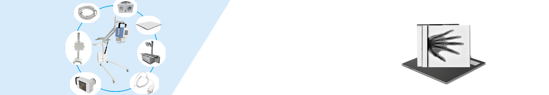
During X-ray exposure, primary X-rays travel straight through the human body and reach the detector to form valid anatomical images. Meanwhile, a large number of scattered secondary X-rays are generated inside tissues, which travel in random directions and overlay the valid image, causing fogging, reduced contrast and blurred lesion details.
The grid consists of hundreds of parallel lead absorber strips and X-ray permeable interspace fillers (aluminum, fiber or carbon fiber). The lead strips block most obliquely incident scattered rays, while straight primary imaging rays pass smoothly through the gaps and arrive at the detector. In this way, image contrast is significantly improved.
2. Why Anti-Scatter Grids Are Indispensable in X-Ray Radiography
- Eliminate image fog caused by scattered radiation, boost the contrast of bone, soft tissue and lesion boundaries;
- Reveal subtle lesions like tiny bone fractures and mild hyperostosis that are easy to miss on plain radiographs;
- Lower the required X-ray output power, helping cut radiation dose to patients under identical imaging quality standards;
- Standardize imaging quality, unify film interpretation criteria for radiologists and reduce misdiagnosis risks.
For thick body parts (abdomen, pelvis, spine, thigh, etc.) with severe scattered radiation, grids are mandatory for routine radiographic examination.
3. Key Technical Parameters of Anti-Scatter Grids (Complete Glossary)
3.1 Grid Ratio
The most core indicator, calculated as the height of lead strips divided by the width of the interspace gap.
- Low ratio (4:1 / 5:1): Weak anti-scatter capacity, suitable for thin limbs and low-kV pediatric radiography;
- Medium ratio (8:1 / 10:1): General clinical universal model, widely used for chest, limb and joint examinations;
- High ratio (12:1 / 15:1): Strong ability to block high-energy scattered rays, applied to abdomen, lumbar spine and thick torso imaging with high kV setting.
3.2 Grid Frequency
Refers to the number of lead strip pairs per centimeter or per inch. Conventional frequencies range from 28 lines/cm to 43 lines/cm.
Higher frequency delivers finer imaging details, but raises processing costs and requirements for positioning accuracy.
3.3 Focal Distance (Focal Range)
Designated valid SID (source-to-image distance) range matched to the grid. If the actual shooting distance deviates far beyond this range, valid primary rays will also be blocked by lead strips, resulting in obvious grid cutoff and partial image loss.
3.4 Material of Interspace Filler
Common options: aluminum alloy, plant fiber, carbon fiber.
- Aluminum filler features stable structure and low price, the most mainstream choice;
- Carbon fiber filler boasts lower X-ray attenuation rate, further reducing patient radiation exposure, used for high-end DR systems.
4. Common Classification & Application Scenarios of Grids
4.1 By Structure Style
-
Stationary Fixed Grid
Fixed inside the examination table or vertical bucky stand, low cost, used for fixed radiography rooms. Minor grid line artifacts may appear on images, which can be eliminated by post-image processing software on modern DR equipment.
-
Moving Bucky Grid (Potter-Bucky Grid)
Driven by a motor to reciprocate horizontally during exposure. Lead strips keep moving rapidly, so grid lines are blurred and invisible on the final image. It is the standard configuration for high-grade stationary DR machines.
4.2 By Lead Strip Arrangement
- Linear Parallel Grid: Universal general-purpose type, applicable to most conventional body part radiography;
- Focused Grid: Lead strips converge toward the X-ray focal spot, fully utilized within the rated focal distance range, higher ray utilization rate;
- Crossed Grid: Two layers of linear grids stacked perpendicularly, excellent anti-scatter performance, only used for ultra-high-definition special examinations.
4.3 By Installation Form
- Built-in grid: Integrated into radiography table / vertical stand, matched with fixed DR systems;
- Portable removable grid: Independent accessory, convenient for mobile X-ray machines, bedside radiography and vehicle-mounted DR equipment.
5. Matching Principles & Usage Precautions for Clinical Use
- Match grid ratio with tube voltage (kV): High kV thick-torso examinations must adopt high-ratio focused grids, otherwise scattered rays cannot be filtered effectively;
- Strictly control the actual SID within the grid’s rated focal distance range to avoid grid cutoff;
- Observe the grid marked focal side (X-ray incidence side). The focal face must face the X-ray tube, reverse installation will cause full-image attenuation and severe underexposure;
- Portable grids should be placed closely against the detector surface, and avoid tilting during shooting;
- For ultra-thin extremities (fingers, wrists), scattered radiation volume is extremely low, and radiography can be performed without a grid to save exposure time and lower radiation dose further.
Closing Summary
The anti-scatter grid is a low-cost but core consumable component that determines X-ray imaging quality. Correct selection, installation and operation directly affect lesion diagnosis accuracy, patient radiation safety and the long service life of DR detectors. It is a necessary basic accessory that cannot be omitted in standardized radiology departments and outpatient clinics.
Post time: Jun-12-2026