
With the continuous advancement of X-ray equipment, DRX radiographic systems have been widely adopted in clinical practice. To better understand their operational characteristics and quality control requirements, we first compare them with traditional X-ray machines and CRX systems, then elaborate on the impact of alignment deviations and the corresponding calibration procedures.
1. DRX vs. Traditional X-Ray/CRX Systems: Core Differences in Imaging Principles
Traditional X-ray machines or CRX systems operate by having a collimator directly irradiate a conventional film cassette (with an intensifying screen) or an imaging plate (IP plate). Since the film cassette or IP plate can be placed directly under the patient, operators can visually confirm the alignment of the collimator with the patient’s affected area.
In contrast, DRX systems project X-rays directly onto a flat-panel detector (FPD). FPDs for DRX typically have a size of over 23 × 23 inches, and the X-ray irradiation field is determined by the selected imaging site (e.g., chest, limbs). For this reason, any deviation among the X-ray irradiation field, X-ray light field, and FPD will cause inaccuracies in the X-ray signals received by the FPD—directly compromising image clarity and diagnostic reliability.
2. Step-by-Step Alignment Calibration for DRX Systems
To eliminate deviations and ensure optimal image quality, the following calibration steps should be performed regularly:
Step 1: Check and Correct the Column’s Horizontal & Vertical Position
- First, verify whether the DRX system’s column is level (horizontal) and plumb (vertical).
- If misalignment is found, adjust the fixing screws at the top of the column to correct its position until it meets horizontal and vertical standards.
Step 2: Inspect Key Components and Reinstall (If Needed)
- Check the installation accuracy of the X-ray tube collimator (or beam limiter) to ensure it is securely and correctly mounted.
- Regularly inspect the balance weights at both ends of the U-arm—imbalanced weights can lead to U-arm tilting and subsequent alignment errors.
- If reinstallation is required (e.g., after maintenance):
- First mount the X-ray tube beam limiter assembly.
- Then install the detector, starting with positioning it in the horizontal orientation before adjusting it to the vertical orientation.
Step 3: Adjust Detector Position and Align Light Field with FPD
- Adjust the screws on the side of the detector assembly to move the detector up or down, ensuring it is at the correct height for imaging.
- Rotate the U-arm to the vertical position and turn on the beam limiter’s field light.
- Align the center of the light field with the central anchor point on the FPD’s upper surface.
- Ensure the horizontal and vertical projection coordinate lines of the light field fully match the area range indicators on the FPD’s upper surface.
- Fine-tune the alignment and safety screws at the four corners of the collimator to achieve perfect alignment between the light field and the FPD.
Step 4: Verify X-Ray Beam Alignment and Center Calibration
- Place the X-ray beam alignment inspection tool on the beam limiter’s inspection fixture.
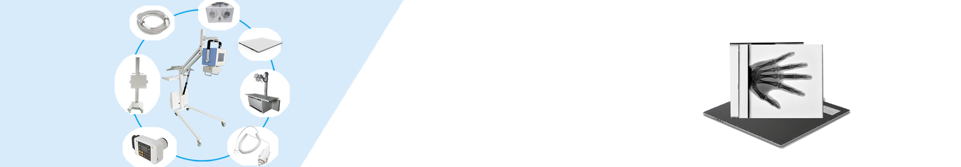
- Activate the X-ray beam and carefully observe whether the projection of the alignment tool on the FPD matches the tool’s scale (ensuring no magnification or offset errors).
- Acquire a test image and adjust the upper spherical marker to the center of the image.
- Calibrate the center of the X-ray irradiation field and the image receiving assembly (FPD).
- Display the acquired test image and confirm that the deviation between the center of the X-ray irradiation field and the center of the FPD is within the allowable range.
3. Contact Us
If you are interested in our DRX radiographic systems, or need further guidance on equipment calibration and maintenance, please feel free to contact us. We provide professional solutions and support to meet your clinical imaging needs.
Post time: Sep-12-2025